
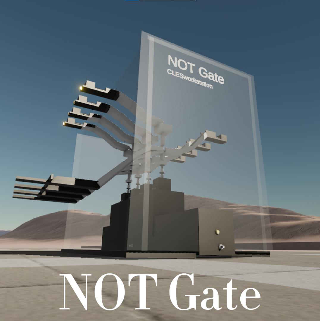
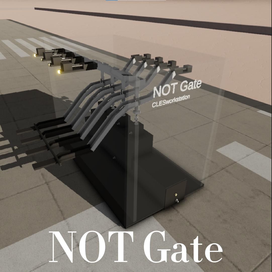
I worked on showing the logic gate circuit in a mechanical way and this is a demonstration of the concept of a stage - a mechanical non-gate which can handle 4 binary digits at a time.
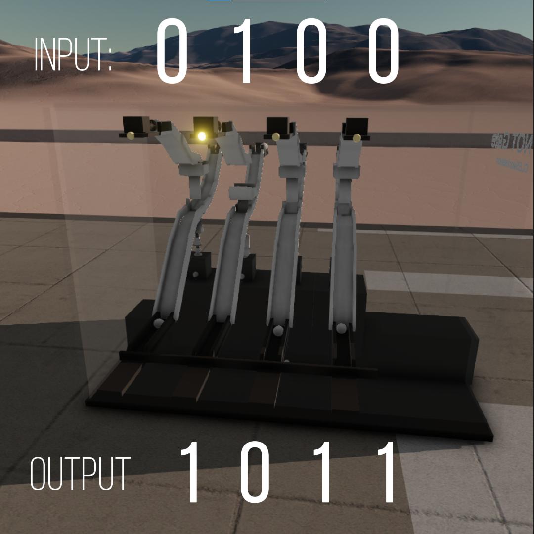
As a non-gate, it will convert your input from 0 to 1 and 1 to 0.
As this is a mechanical logic gate, we use the "ball with no ball" pattern instead of the "high voltage low voltage" pattern of a real logic gate.
How to use:
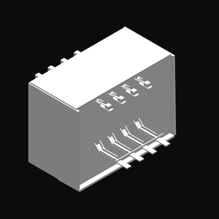
Control the four inputs via AG1-AG4, then use slide 2 to push the "input ball" into the operator.
Use slider 1 to push the "drive ball" (instead of the constant current in the real circuit) into the operator.
Check the output in the output port below.
Principle.
When the input ball enters the basket, the basket with the ball will depress the spring and the gate will be lowered, blocking the "drive ball" and constituting a "no ball" or "0" output at the output port.
If "no ball" is input, the "drive ball" rolls into the output port and constitutes a "ball" output, i.e. a "1".
This results in a non-gate operation
Notes.
Please excuse the unstable operation due to the game wearing the mould.
GENERAL INFO
- Created On: Windows
- Game Version: 0.9.704.0
- Price: $1,323k
- Number of Parts: 358
- Dimensions: 11 m x 13 m x 14 m
PERFORMANCE
- Total Delta V: 0m/s
- Total Thrust: 0N
- Engines: 0
- Wet Mass: 1.56E+5kg
- Dry Mass: 1.05E+5kg
STAGES
| Stage | Engines | Delta V | Thrust | Burn | Mass |
|---|


Hmm, not a gate…